Friday 21 October 2011

Evaluation of modelling the Head

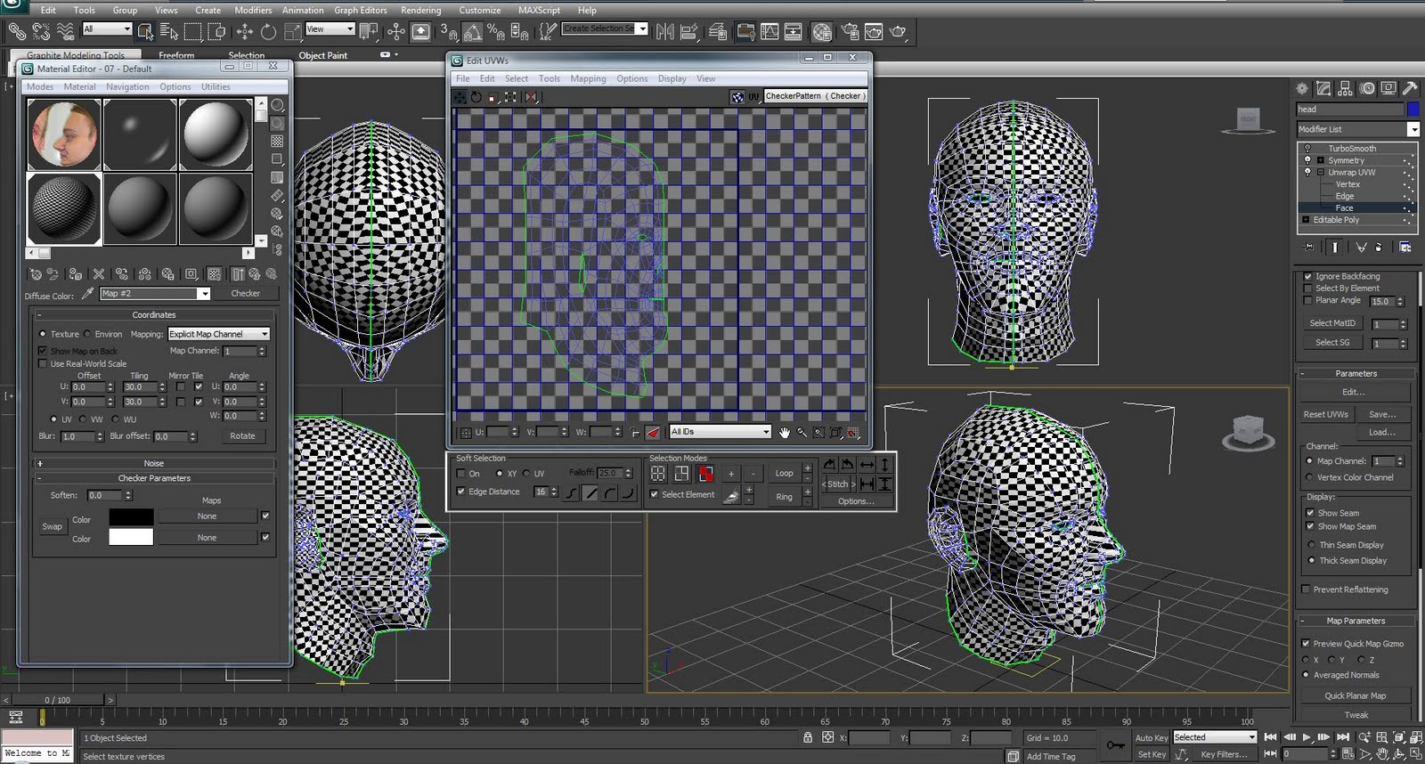
The head model is all finished. I can say that I am quite satisfied with the final result. At the end I managed to do some extra work by adding hair and beard which gave a really nice look. The head model definitely looks similar to me. As this was the main purpose of the module part i consider it to be successful. I am pleased that I have managed to learn new modelling technique. The organic modelling approach appears to give a lot of focus on preparation stage. Creating the topology using reference images is not an easy task. But after few tries you start to notice various lines and the flow of the object. One thing to mention as well was that after drawing all these topology lines I began to notice vital parts of the head that define the head and individual person. I also learned how to create uvw coordinate layout of the model. This is not very exiting part but it gives a lot of freedom and detail in further texturing process. As well creation of head focused on creating different texture maps. I learned how using reference images I can build texture map according to the UVW map template. Also I learned how to create bump and specular map.

The whole process of modelling head went smooth. Except the last hair part and few small glitches mentioned earlier. At this point my laptop was not able to cope very well and 3d max used to crash. Good thing that I did hair last and it did not disturb the process of modelling. I endede up redoing such parts as creating topology for face and ear. However, I feel that I am much better at it. Eventually I feel that my 3D modelling and texturing skills have improved and I look forward to starting group project.

Also I wanted to do some face expressions and animate the head with a morph modifier. However, I did not have enough time to do it and even the idea of rendering animated head with hair gives me a headache as it takes a lot of time to render a single frame. I wanted to add eyebrows, eyelashes and my earring, but everything adds up to lack of time and deadlines. Nevertheless, I managed to finish all tutorials and execute them quite good.
Some final renders of the head for the end.

Thursday 20 October 2011

Hair and Eyeball

With my model all finished up I still had time to add some extra detail to it. The necessity to the model are eyeballs. It is really strange when you look at model which has empty holes instead of eyes. The eyeballs was quick and easy part. First I created a sphere. I moved and transformed the sphere to fit in the eye socket area. Then I got iris photo from the Internet. I loaded the image as bitmap map to material editor empty slot. Then I applied the new material to the sphere. The uvw map modifier was applied to the sphere. This allowed me to move map gizmo around to position iris in the right place. Then I copied the finished eyeballs for the left side.


The long hair of the head were created using splines. I froze the head model and turned snap to faces tool. Then I started creating lines. These lines are suppose to build the flow of the hair. I started drawing from top hairline to the back of the head. I kept on doing this around the whole head. Then I attached all splines together. While in points sub-object menu I started moving various points away from the head and correct the flow of the lines. Then I applied hair and fur modifier and adjusted the settings to match my preferences. After checking the render I moved some of line points around, changed some more settings and got a decent looking hair.


For the short hair which are next to an ear I decided to use different method. I applied hair and fur modifier to the head model. Then I selected the faces where the hair is going to be placed and updated the selection. After changing settings to hair modifier I switched to style mode. There I managed to change the position and flow of the hair with translate option. Aswell I used same method for my tiny beard. The rotation tool was great help at making the beard to face right direction. Then I used hair cut tool to trim and shape my beard. I found the style hair mode options very useful and easy for changing hair styles.


Week4. Specular map

The specular map is going to be created using previous bump map. In Photoshop the dark colour were brought in with image>adjustments>levels. All the white spots in the image is going to be specular areas. Then with brush tool I started to draw around eyes, forehead, cheeks, chin, mouth and nose. Then the brush strokes were blurred from filter>blur>gaussian blur. When brought to 3d max the specular map gave very dirty effect. This happened because of various white spots in a specular map. Therefore, the bump image was removed and I created new layer with solid black color over it.


Week4. Bump map

Bump map is going to be created from the head texture map. First I removed all color from the image by going to image>adjustmenet>desaturate. After that the levels of the image were changed from image>adjustment>levels. Then the high pass filter was applied by going to filter>other>high pass. Then in a new layer using brush tool I draw some white circles in mole areas.


The bump image was uploaded to head material bump map. Once rendered the bump map makes skin look very rough. To minimise this effect I choose mix map at bump map options. Second color was set with noise map. Then in noise parameters fractal was chosen and size was set to 0.1. Back in bump map mix amount was set to 60. When rendered bump effect looks much more blended with whole skin map and all roughness is gone.

Week4. Creating bitmap Texture

The texturing part was made in Photoshop. It began by opening uvw wireframe image which was created in last tutorial part. The image is going to be used as a guide for creating the head texture. New layer was created and filled with blue color. Then the uv image was copied and pasted to a new layer while in quick mask mode. After exiting the quick mask mode the wireframe lines became selected. Selected lines width were made bigger to 4 pixels by going to select>modify>border. Then the layer mask was added to the layer. The masked layer was turned to regular layer by applying layer mask. This layer is going to be used as a guide to know where different parts of the head texture should be.


Then the reference images of the head were loaded to the photoshop. Using lasso tool I started to select different areas from the reference images such as eyes, nose, forehead, mouth, etc. and copied them to texture file. Each part was moved around, transformed and warped to match the wireframe guide. Once main part of the head was covered I started to match the color of the face copies by changing hue/saturation settings. Then all layers that consist parts of head texture were selected and merged together.


At this point I had a lot of gaps between various parts of the head. The gaps were filled using stamp tool. It is a very handy gadget which lets to sample required area from the image and copy/stamp to the are you want to. After all parts of the head map were covered I started to clean up and fix some parts. I used spot healing brush tool to fill tiny holes which were not covered. Then using patch tool I removed the visible color difference at samples connection points.


For the ear I copied ear part from the reference image. Then using warp tool I managed to transform ear section to match the ear polygons. Then I copied extra texture for parts that are not so visible and cleaned everything up with patch tool.


The bitmap image was loaded to 3d max an applied to the face. At this point I noticed few errors. First was the problem with a symmetry modifier. One of the polygons instead of having original 4 vertices got 5 which gave noticeable gap when texture was on. I tried going back to original editable poly modifier to fix it up but the whole uvw mapping got messed up. The problem was simply solved by applying new editable poly modifier after unwrap uvw modifiers and then selecting unwanted vertex and removing it with vertex remove tool. Second problem occurred with in nostril area. While unwrapping uvw I did not pay attention that there was a seam inside the nostril. The polygons in nostril did not have any uvw mapping. Therefore I applied extra unwrap uvw modifier and selected faces in the nostril. Then I applied planar map, scaled down and moved them to nose area in the uvw coordinates. The color match is not perfect but it is much better than having the whole bitmap image showing up inside the nose.


And render of model with the texture.


Wednesday 19 October 2011

Week3. setting up Mapping Coordinates

The modelling of the head is finished at this stage. Next step is to set up the mapping coordinates. It have started by applying Unwrap UVW modifier after editable poly modifier. The symmetry will be used later on to duplicate the mapping on the other side of the head model. When in unwrap uvw modifier sub-object mode I selected Face and selected all polygons of my head except the ear. With polygons selected I used cylindrical in map parameters. Then I scaled and moved the cylindrical gizmo to fully cover the head model and moved it to the edge of the model to have one solid seam. Then in material editor window the checkers texture was created by selecting an empty sample slot and applying checker map in diffuse options. The tiling parameter was increased to 30. The material was applied to head model by dragging it on the head. This map was used to see where unordinary stretches occur in the mapping. Back in UWV modifier edit uvw window was opened from parameters sub-menu. In edit UWV window Options menu tile bitmap checkbox was unselected and constant update was checked in order to see how changes in mapping affect model in the viewport. To start with setting up texture coordinates I selected all head faces and and flipped them horizontally with mirror tool. Then I started to select the vertices where map stretching is unordinary and started to relax them with relax tool from tools menu. With relax tool I fixed parts at top of the head and neck also areas around the nose and chin. Then I kept on moving vertices around the eye area and nose to clean up small errors in the mapping. Then I checked if there are any inverted or overlapped faces in the mapping and fixed them accordingly until I was satisfied with mapping.


The next part was to set up mapping coordinates for the ear. The ear polygons were selected and planar fit was selected in map parameters sub-menu. Then Pelt was selected and new break point for the ear map was created with point to point seam. Then in Pelt edit uvw window the outer ring was scaled and shaped as a circle. Back in Pelt dialog box start pelt was selected to make ear map flat. Then the ear map was scaled down to match the map of the head. Then ear UVW map was cleaned up by moving some points and fixing overlapped and inverted faces.

To create the UVW mapping on the duplicated head part the new unwrap UVW modifier was applied after the symmetry modifier. Then faces of the symmetry part were selected and mirrored to the other side. The layout was positioned next to the original map. Then maps were connected together by welding vertices in the center of the face. Afterwards the map layout for duplicated ear was created using same method as for the head.


The UVW layout was scaled down to fit mapping box. The layout was turned to an image by going to tools>render UVW template. The created image is going to be used in a Photoshop as a guide for creating head map texture.

Sunday 16 October 2011

Week3. Ear.

I was not looking forward to modelling the ear as the shape appeared to be very difficult with all the curves and bumps inside. I have found the ear part to be very challenging. At the end i had to do my ear again cause the first one looked very disappointing. I am putting few images from the first attempt.


When drawing a topology in photoshop for the first ear I have tried to keep the quad number to minimum. This caused some problems while creating the curves and bumps in the 3d max. So after playing around and moving the vertices I eventually decided to create new topology with more detail/quads in it.


With new topology I started creating splines in the 3d max. To ease the process I turned the snaps toggle with snapping set to vertex. Then I selected one of the splines and converted it to editable poly. I attached other splines using attach tool. Using weld tool i welded the multiple vertices. Once I had the solid ear mesh I have started to move vertices on x axis to give the depth to the mesh.


After a while the mesh got a shape of the ear. Then using polygon inset tool I created more polygons for the inside of the ear. This allowed to give more detail to ear.


I created few more polygons with create tool in polygon mode. They were used to connect ear to the head. Then I created the back of the ear by selecting open edges and shift dragging them twice. With scale tool I managed to move the edges inside. Then I created new polygons to decrease number of vertices that are going to be connected with the head. Then I aligned the vertices that are going to be connected with the head and attached ear to head. Finally I welded the vertices and got finished head model.


Here is the image with finished head model and first ear model on the left.